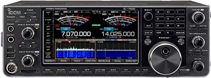
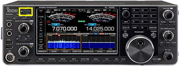
Icom IC-7610
IC-7610 operating guide
This transceiver is currently connected to the NARC1 station computer.
Icom manuals
Here are links to the IC-7610 manuals:
Starting up
- The IC-7610/NARC1 is located closest to the main door off the porch.
Connect equipment and power-up
We have been experimenting with remote control of some station operations, including powering on the rig power supplies. As a result, the next set of actions may or may not be required.
- Connect to the power mains.
- Power cables are located between the wooden shelf and the east wall.
- Plug the large 240 V cable (green tag) for the amplifier power supply into the 240 V wall outlet.
- Plug the smaller 120 V cable for the Uninterrupted Power Supply (UPS) into the 120 V wall outlet.
- Connect the radio to a suitable antenna.
Before you power up the radio, connect it to a suitable antenna.
The antenna connections are located on the north wall, near the repeater cabinet. Choose the PL-259 connector with the yellow IC-7610 tag. Plug the cable from the radio into the cable connector for one of the antennas, for example, one of the triband Yagis for 10-20 m.
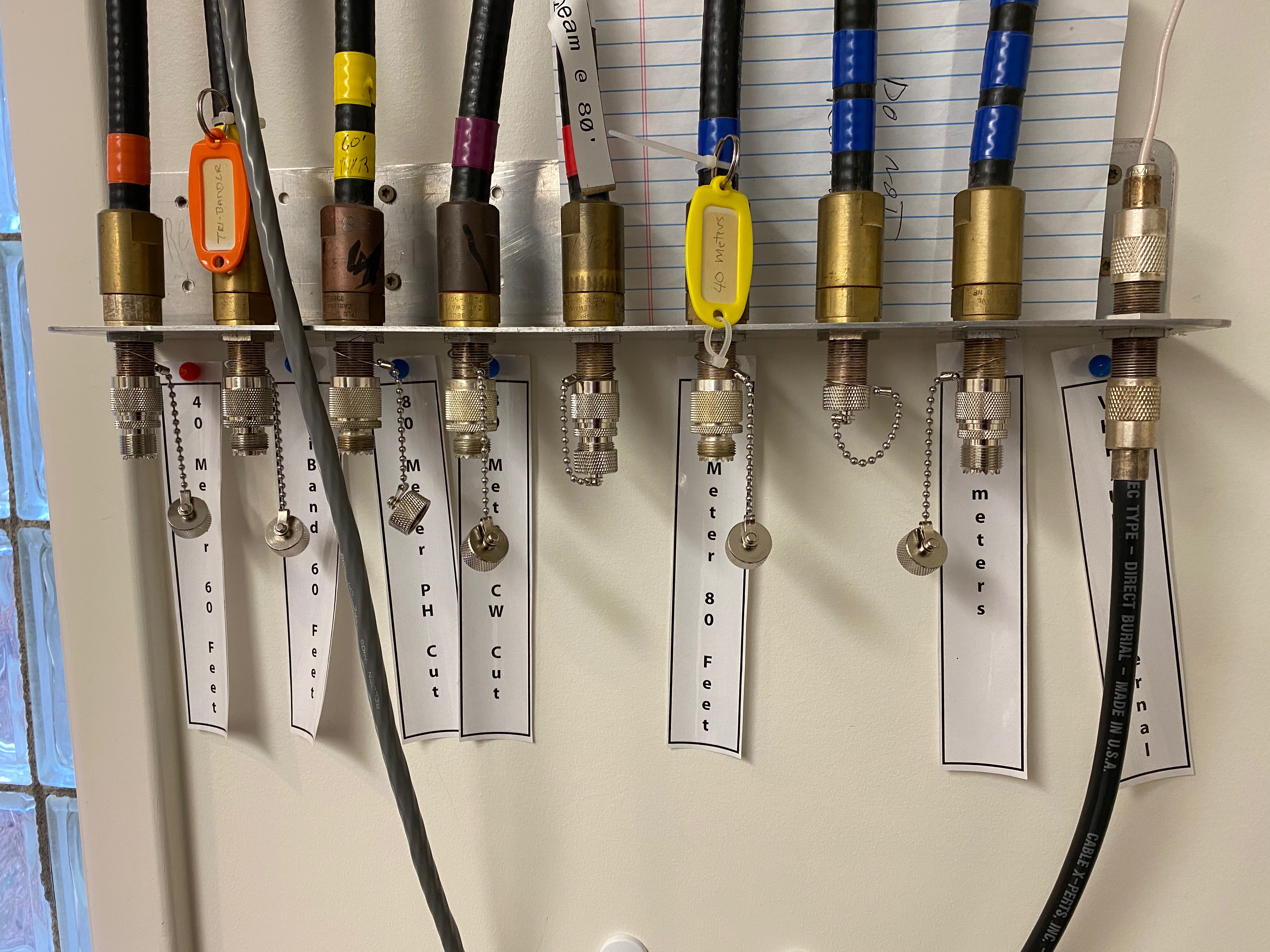
Please do not remove the N/PL-259 connectors from the antenna feedlines.
Power up the UPS by pushing the front button. The green power light should illuminate.
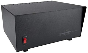
Power up the Astron RS-35A power supply that powers the IC-7610/NARC1. The power supply is located to the right of the Elecraft KPA1500 amplifier.
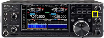
- Power up the IC-7610/NARC1 by pressing and briefly holding the power button highlighted in Figure 7.4.
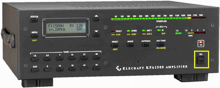
- Power up the Elecraft KPA1500 amplifier
The IC-7610/NARC1 is connected to the Elecraft KPA1500 amplifier. The power supply for the KPA1500 is under the desk on a small footstool. Check that the KPA1500 power supply is on. If necessary, power-up the power supply by hitting the power switch on the upper rear left side of the power supply. When the amplifier power switch is on, you will see 3 green lights: AC on, High V supply, Low V supply. Power up the KPA1500 by pressing the on switch on the lower right hand side of the KPA1500 front panel as shown in Figure 7.5.
If you are not operating with more than 100 W or do not need the KPA1500’s built in antenna tuner, then leave the KPA1500 powered off.
Log-in to the computer
Power up the PC by pressing the power button on the right rear panel.
Log-in using the appropriate password
The IC-7610/NARC1 is connected via USB2 to the NARC1 PC. Open your logging program of choice. NARC has licenses for N1MM and N3FJP’s Amateur Contact Log.
To operate digital modes (e.g., FT8/FT4, JS8Call, fldigi), open those programs. See instructions for operating these modes in separate sections below.
Basic controls
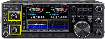
- Audio levels for the two VFOs are controlled via separate knobs on the left side of the front panel as shown in Figure 7.6.
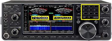
- As shown in Figure 7.7 You may switch operating bands in one of two ways:
- Buttons located on the right side of the front panel
- Pressing the frequency on the touch screen.
- Switch operating modes by pressing the mode button on the touch panel as shown in Figure 7.8.
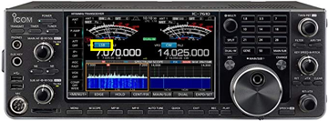
This opens a window where you can choose the mode of operation. - Hit the arrow button to close the window and save your choice.
- Turn digital noise reduction on or off by pressing the NR button on the left side of the front panel highlighted in Figure 7.9. When NR is on, the NR button will be illuminated.
- To adjust the amount of noise reduction, press and hold the NR button to open a window on the upper right corner of the touch panel display.
- Turn the MULTI key to adjust the level of noise reduction.
- Close the NR window by pressing the MULTI key or by pressing the NR button.
- Adjust preamplifier (
P.AMP) settings, automatic gain control (AGC), Intercept Point (IP+),VOX, and compression (COMP) settings by pressing the corresponding button on the left side of the touch/display screen.
- Adjust touch/display screen settings via the MENU1/MENU2 buttons at the bottom of the touch/display screen illustrated in Figure 7.10.
- Select receive filter settings via the
FILTERbutton on the right side of the front panel, below theTWIN PBTknob as highlighted in @ic-7610-filter.
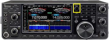
- Set RF power by pressing the MULTI button to open a window on the display/touch screen. Press the RF POWER panel to select it, and adjust the output power by turning the MULTI knob as shown in Figure 7.11.
Settings
The rig and computer settings are tested on a regular basis, approximately monthly. If you would like to help W3TM test the rigs or improve and update the documentation, let him know.
Please do not change any software or rig settings without:
- Contacting W3TM 814-777-3298 first OR
- Documenting your changes in detail
The following setting parameters are provided for reference:
- A single USB A/B cable connects the rig to the PC.
- COM3 is used for most CAT control. The IC-7610 creates a second COM port that is currently unused.
- 8-N-1 at 38400 baud is used for serial control.
- Audio in/out are via USB Audio CODEC. The ICOM driver has been installed.
Phone operations
On the PC
You do not need to use the PC to operate phone, but you may want to use the PC for logging.
Power up the NARC-1 PC by pressing the power button on the front panel.
Log-in using the appropriate password
Open your logging program of choice. NARC has licenses for N1MM and N3FJP’s Amateur Contact Log.
N1MM
Please do not update N1MM without asking Mike N3LI, Rick W3TM, or Eric W3EDP first.
Amateur Contact Log (ACL a.k.a. N3FJP)
You may need to download the specific log for the contest you want to work. The club has paid N3FJP for a license under the W3YA callsign. Ask W3TM for information about the license codes for contests that are are not already installed.
- Open Amateur Contact Log
- Confirm that the program tracks frequency & mode.
On the IC-7610
- Confirm the rig is in SSB mode.
To change the mode, press the mode indicator on the touch screen to open a window to toggle the mode (USB/LSB) appropriate for your band.
Remember, the convention is to use LSB below 10 MHz except for 60 m.
- Set your receive bandwidth by pressing the FILTER button located on the right side of the front panel.
You may adjust the filter settings by pressing and holding the filter button on the right side of the rig control panel. Press and hold the FILTER button on to save and apply the filter settings.
Check audio output levels.
Set desired RF power output using MULTI knob.
Press and hold the MULTI button to open a window on the touch/display screen. Press the RF POWER panel and rotate the MULTI button to set RF power.
On KPA1500
- For < 100W output, set amplifier to STBY mode (yellow light) by pressing MODE button to toggle between STBY and OPER.
For higher power output, follow these instructions for tuning the KPA1500 amplifier.
Confirm ANT1 is output (press ANTENNA to toggle).
Confirm ATU is IN (not BYP) by pressing and holding ATU TUNE button.
Digital mode operations
The setup for each digital mode is slightly different, so we have created separate sections to describe those operations.
Fldigi suite
As of 2023-12-19, the installed version of fldigi is 4.1.26.
On the PC
- Open fldigi. (Icon is on desktop.)
Fldigi is configured to use the flrig program to interface between the radio and the computer. Flrig should open automatically a few seconds after fldigi opens. If flrig shows the current VFO frequency and so does fldigi, the two devices are talking to one another.
- Confirm Settings
It’s not essential to confirm the settings each time you start up, but doing so will make sure that you are able to operate without difficulty.
In flrig, open the Config menu and select Setup > Transceiver. This opens a separate window.
| Parameter | Value | Comments |
|---|---|---|
| Rig | IC-7610 | |
| Ser Port | COM3 | |
| Baud | 38400 | |
| Parity | N or none | |
| (Stop bits) | 1 | |
| PTT via CAT | \(\checkmark\) | |
| CI-V adr | 0x98 |
You may now close the Configuration window by pressing the CLOSE button or close window (X) button.
- Check receive operations
- Turn to a known PSK31 frequency, for example, 14.070 MHz in the 20 m band.
- From the fldigi Op Mode menu, select PSK > BPSK-31
If all is well, you should see decodes in the left hand window and signals in the waterfall below.
- Configure your operational settings.
- From the Configure menu, select UI > Operator to open a window.
- Under the Operator tab set Station Callsign, Operator Callsign, Operator Name, Antenna, Station QTH, Station Locator and other items.
On the IC-7610
- Confirm rig is in USB Data 2 (USB-D2) mode.
To change the mode, press the mode indicator on the touch screen to open a window to toggle the mode (USB/LSB) to USB. Unless you are sure that your digital mode uses LSB, select USB. Press and hold the DATA button to switch between D1, D2, and D3 data mode connectors. D2 is configured for use via USB.
- Set your bandwidth to filter 1 (wide) by pressing the FILTER button located on the right side of the front panel.
You may adjust the filter settings by pressing and holding the filter button on the right side of the rig control panel. Press the arrow/return button on the display/touch screen to save and apply the filter settings.
- Set other settings
The following settings can be changed via buttons on the left side of the touch/display screen.
- Preamp (P.AMP) off
Press the P.AMP button to cycle through the settings (OFF, P.AMP 1, P.AMP 2)
- Attenuator (ATT) off
Press the ATT button to cycle through the attenuator settings (OFF, 6 dB, 12 dB, 18 dB)
- IP+ off
Press the IP+ button to select ON or OFF
- Turn Automatic Gain Control (AGC) off
Press and hold the AGC button on the display/touch screen. This opens a panel. Under the SSB column, select the SLOW setting. Adjust the AGC level downward until the indicator says OFF. Press the arrow/return button on the display/touch screen to enter the setting.
VOX off
Noise reduction (NR) off
Press the NR button on the left side of the front panel to turn off the illuminator.
- Noise blanker (NB) off
Press the NB button on the left side of the front panel to turn off the illuminator.
- Set desired RF power output using MULTI knob.
Press and hold the MULTI button to open a window on the touch/display screen. Press the RF POWER panel and rotate the MULTI button to set RF power.
Generally speaking, 40-50 W RF output is more than sufficient for successful operation using fldigi-supported modes.
On KPA1500
It’s possible to use the amplifier for fldigi-supported modes, but we do not recommend it. These modes involve high duty cycles and put a lot of stress on the amplifier.
WSJT-X
The current installed version as of 2023-12-19 is v2.5.4.
On the PC
- Open WSJT-X (Icon is on desktop.)
WSTJ-X opens to the same operating frequency as the rig is on when you start.
- Confirm Settings
It’s not essential to confirm the settings each time you start up, but doing so will make sure that you are able to operate without difficulty.
Open the Configurations menu and select a configurations set.
Standard Opsis a good place to start.Open Settings from the File menu
General tab:
Set My Call to your personal callsign unless you have permission to use the club callsign (W3YA). Set any Display or Behavior settings per your personal preferences.
Radio tab:
Change these at your own risk.
| Parameter | Value | Comments |
|---|---|---|
| Rig | Icom IC-7610 | |
| Ser Port | COM3 | |
| Baud | 38400 | |
| Data Bits | 8 bits | |
| Parity | none | |
| (Stop bits) | 1 | |
| Handshake | none | |
| Force Control Lines: | unset | |
| PTT method | CAT (port should be COM3) | |
| Mode | Data/pkt | |
| Split operation | Rig or Fake It |
You may want to check/confirm that rig control is working by pushing the Test CAT button in this panel. If the button turns green, then the rig and computer are communicating.
You may also want to check that PTT is working. Adjusted the rig’s power output to a low level (1-5 W) before testing. On the IC-7610, press the MULTI button, touch the RF Power panel on the touch screen, and turn the MULTI button to set desired output power.
Press the Test PTT button and observe whether the transmitter keys up. If so, all is well.
Audio tab:
| Parameter | Value | Comments |
|---|---|---|
| Input | USB Audio Codec | |
| Output | USB Audio Codec |
Reporting tab
You may want to set the Op Call to your own callsign.
Advanced tab:
Check or uncheck Special Operating Activity per situation, for example ARRL Field Day or the NA VHF Contest.
You may now close the Settings window by pressing the OK button.
Switch to the desired mode (e.g., FT8) from the Mode menu. Select the desired operating band and default frequency from the dropdown menu on the lower left side of the main WSJT-X application panel.
- Check computer clock accuracy
Open a browser; visit https://time.is
If your time synch is within .5s of the correct time, you may proceed.
If you are decoding signals in the waterfall, then all is well.
On the IC-7610
- Confirm rig is in USB Data 2 (
USB-D2) mode.
To change the mode, press the mode indicator on the touch screen to open a window to toggle the mode (USB/LSB) to USB. Unless you are sure that your digital mode uses LSB, select USB. Press and hold the DATA button to switch between D1, D2, and D3 data mode connectors. D2 is configured for use via USB.
- Set your bandwidth to filter 1 (wide) by pressing the FILTER button located on the right side of the front panel.
You may adjust the filter settings by pressing and holding the filter button on the right side of the rig control panel. Press the arrow/return button on the display/touch screen to save and apply the filter settings.
- Set other settings
The following settings can be changed via buttons on the left side of the touch/display screen.
The following settings let the software do the heavy-lifting.
- Preamp (P.AMP)
off
Press the P.AMP button to cycle through the settings (OFF, P.AMP 1, P.AMP 2)
- Attenuator (ATT):
off
Press the ATT button to cycle through the attenuator settings (OFF, 6 dB, 12 dB, 18 dB)
- IP+:
off
Press the IP+ button to select ON or OFF
- Automatic Gain Control (AGC):
off
Press and hold the AGC button on the display/touch screen. This opens a panel. Under the SSB column, select the SLOW setting. Adjust the AGC level downward until the indicator says OFF. Press the arrow/return button on the display/touch screen to enter the setting.
VOX:
offNoise reduction (NR):
off
Press the NR button on the left side of the front panel to turn off the illuminator.
- Noise blanker (NB) off
Press the NB button on the left side of the front panel to turn off the illuminator.
- Set desired RF power output using MULTI knob.
Press and hold the MULTI button to open a window on the touch/display screen. Press the RF POWER panel and rotate the MULTI button to set RF power.
Remember, WSJT-X is a weak signal mode. Less than 50 W is plenty, especially if you are using one of our “gain” antennas (Yagis).
On KPA1500
It’s possible to use the amplifier for fldigi-supported modes, but we do not recommend it. These modes involve high duty cycles and put a lot of stress on the amplifier.
Operating hints
- Make sure that your audio input level is not too high.
There are several ways to adjust this: - Adjust the RF/SQL button on the rig - Adjust the mic levels on the PC (open the Audio control panel)
CW operations
Coming soon!